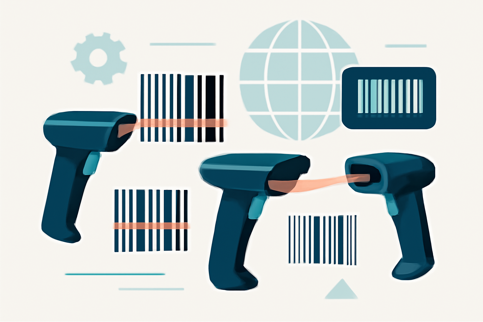
Barcode Readers and Scanners - Equipment Guide
Barcode readers and scanners translate printed patterns into digital data — choosing the right equipment depends on your symbology requirements, reading distance, and environmental conditions. This guide covers scanner technologies, selection criteria, and integration options based on real implementation needs across retail, manufacturing, and logistics environments.
Barcode Scanner Types and Technologies
Modern barcode readers use three distinct optical technologies, each with specific performance characteristics. Laser scanners employ a moving beam to illuminate one line of a barcode at a time, reading linear symbologies like Code 128 and Code 39 at distances up to 24 inches. They’re fast, accurate, and cost-effective for high-volume retail applications, but they cannot read damaged codes or 2D symbologies.
Linear imagers use LED illumination and a single row of photosensors. They capture a digital image of the barcode, allowing them to read codes from screens, through plastic packaging, and even poorly printed labels that defeat laser scanners. The image capture approach also enables omnidirectional reading — no need to align the scanner perpendicular to the bars.
Area imagers represent the current standard for versatility. These devices use a 2D sensor array (similar to a camera) to capture the entire barcode in one exposure. They read every common 1D symbology plus QR codes, Data Matrix, PDF417, and other 2D codes. Area imagers handle damaged barcodes better than laser scanners because they capture redundant data across the entire symbol. Most modern implementations use area imagers unless budget constraints or specific reading distance requirements dictate otherwise.
The decoding happens in milliseconds. The scanner’s processor analyzes light and dark patterns, applies error correction algorithms, and outputs ASCII data through the interface. Quality scanners decode according to ISO/IEC 15426 specifications, which define minimum performance thresholds for various symbology types.
Handheld and Fixed-Mount Readers
Handheld scanners dominate retail and light industrial use. Corded models connect via USB or RS-232, drawing power from the host system — they’re reliable and require zero battery management. Wireless models use Bluetooth, with batch memory storing hundreds or thousands of scans when the host device is out of range. Range varies from 30 feet (Class 2 Bluetooth) to 300+ feet (industrial radio frequency models).
Form factors matter more than most buyers realize. Pistol-grip scanners reduce wrist strain during high-volume scanning. Presentation scanners sit on countertops, reading codes automatically when items pass through the scan field — grocery checkouts use this approach. Ring scanners mount on a finger, leaving both hands free for package sorting operations that require 8+ hours of continuous use.
Fixed-mount readers install on conveyor systems, production lines, and automated gates. They trigger on object detection sensors, capturing codes as items move through the read zone at speeds up to 500 feet per minute. These systems typically use multiple scan heads positioned at different angles to ensure six-sided coverage on boxes and packages. Integration requires understanding of industrial protocols — most fixed-mount readers communicate via Ethernet/IP, PROFINET, or discrete I/O signals that integrate with PLCs.
The housing specification matters in industrial environments. IP65-rated enclosures resist water and dust. IP67 units survive temporary immersion. Temperature ranges extend from -20°C to 50°C for freezer and outdoor applications. Drop specifications typically range from 4 feet (light duty) to 8 feet (rugged) onto concrete.
Scanner Selection Guide
Match the scanner technology to your symbology mix. If you only scan UPC codes on retail products, a basic laser scanner works fine. Distribution centers handling mixed packaging with both 1D and 2D codes need area imagers. Healthcare applications requiring Data Matrix codes on pharmaceutical vials demand high-resolution 2D imagers.
Reading distance determines the required optical specifications. Contact scanners (0-2 inches) use shorter focal lengths for small codes. Standard range (2-18 inches) covers most handheld applications. Extended range models (up to 50 feet) use telescope optics for warehouse rack scanning or overhead conveyor reads.
Environmental factors drive significant cost differences. Standard scanners fail in cold storage, outdoor use, or wet environments. Sealed housings add 50-100% to equipment cost but eliminate downtime from environmental damage. Honestly, most implementations underestimate environmental requirements — then buy twice.
Decode performance specifications separate adequate from excellent scanners. Look for first-pass read rates above 95% and depth of field measurements that match your application. A scanner rated for 5-mil codes won’t reliably read 10-mil codes at maximum range, despite what sales literature implies. The Print Quality Guidelines in ISO/IEC 15416 define grading methods — specify scanners tested against actual code samples at your expected quality grades.
Interface compatibility requires attention during procurement. USB-HID (keyboard wedge) works for simple point-of-sale applications but limits data formatting options. RS-232 serial provides more control over data formatting and handshaking. USB-COM emulation offers serial flexibility with modern USB hardware. Industrial applications need Ethernet interfaces for network integration and remote management.
Vendor and Product Information
The major manufacturers segment into consumer, commercial, and industrial tiers. Honeywell, Zebra, and Datalogic dominate the industrial market with readers certified for hazardous locations and extreme environments. Their product lines include fixed industrial scanners that cost $3,000+ and integrate with factory automation systems.
Cognex and Keyence specialize in machine vision systems that combine barcode reading with inspection capabilities. These devices cost $5,000-$15,000 but replace multiple single-function devices in automated production lines. They read severely damaged codes that defeat conventional scanners by using advanced image processing algorithms.
Socket Mobile and Linea Pro focus on smartphone-connected scanners for mobile workforces. These sled-style devices add professional scanning capabilities to iOS and Android platforms, running $300-$800 depending on scan engine and battery capacity.
Budget considerations span three magnitudes. Basic USB laser scanners start at $50-$100 for retail use. Commercial-grade wireless 2D imagers cost $300-$600. Rugged industrial scanners with extended temperature ranges and IP67 sealing run $600-$1,200. Fixed-mount industrial imagers with high-speed processing and specialized optics cost $2,000-$5,000 per unit.
Support infrastructure matters as much as initial equipment cost. Specify advance replacement warranties for operations where downtime costs exceed scanner value. Major vendors provide API documentation and SDK support for custom integration projects.
Integration and Connectivity Options
USB interfaces dominate modern installations. USB-HID mode emulates a keyboard — scanned data appears as typed characters with no driver installation required. This works for simple data entry but provides no control over prefixes, suffixes, or data formatting. USB-Serial (Virtual COM) mode creates a standard serial port that application software controls through conventional serial commands. USB requires host power, limiting cable length to 15 feet without active repeaters.
Serial RS-232 connections persist in industrial settings because of noise immunity and long cable runs (up to 100 feet). Most readers default to 9600 baud, 8 data bits, no parity, 1 stop bit (9600-8-N-1), but support rates to 115,200 baud for high-speed applications. Wiring requires only three conductors (TX, RX, GND) for basic operation, plus hardware handshaking for applications requiring flow control.
Bluetooth wireless eliminates cables at the cost of battery management. Class 2 devices provide 30-foot range suitable for retail and light warehouse use. Industrial radio frequency models extend range to 300+ feet and penetrate metal rack structures that block Bluetooth signals. Battery life varies from 8 hours (continuous use) to multiple days (intermittent use). Batch mode stores thousands of scans in internal memory when the host is out of range.
Ethernet connectivity supports fixed-mount installations where readers function as network devices with IP addresses. These units send scan data through TCP/IP sockets or web services, enabling centralized data collection from distributed scanning points. PoE (Power over Ethernet) eliminates separate power supplies, simplifying installation in warehouse rack systems and production lines.
Application integration requires protocol configuration. Most readers support multiple output modes — keyboard wedge, serial stream, or structured data packets. Prefix and suffix strings allow embedding scan data in application commands. Code ID characters identify the symbology type, letting software route UPC scans differently from 2D Data Matrix codes. Some applications need timestamp data included with each scan, requiring readers with internal real-time clocks.
Frequently Asked Questions
Q: What’s the difference between 1D and 2D barcode scanners?
1D laser scanners read only linear barcodes (UPC, Code 39, Code 128) by sweeping a laser line across the bars. 2D area imagers capture the entire barcode as an image, reading both linear and matrix codes (QR, Data Matrix, PDF417). If you need to read codes from phone screens or capture 2D symbologies, you need an area imager. Laser scanners work fine for retail UPC scanning where cost matters more than versatility.
Q: Can I use a barcode scanner with any software?
Most scanners emulate keyboard input (USB-HID mode), making them compatible with any software that accepts typed text. The scanner sends data as if someone typed it, followed by an Enter key. This works for web forms, spreadsheets, and simple inventory programs. Custom applications requiring prefix/suffix formatting or specific data processing need scanners with programmable output modes and may require serial or API integration instead of keyboard emulation.
Q: How do I choose between wireless and corded scanners?
Corded scanners eliminate battery management and cost 30-50% less than wireless equivalents. Use them for fixed workstations where mobility doesn’t matter — retail checkouts, receiving desks, laboratory stations. Wireless scanners justify their cost when operators move more than 10 feet from the host system or when cables create trip hazards or tangle with materials handling equipment. Calculate the operational cost of battery replacement (typically every 18-24 months) when comparing total ownership costs.
Related Articles
- 2-Dimensional Bar Code Page - Specs & Standards Guide
Complete technical guide to 2D barcodes including QR Code, Data Matrix, and PDF417 specifications, implementation requirements, and practical use cases for supp
- BarCode 1 - Comprehensive Barcode Information Resources
BarCode 1 provides technical specifications, standards documentation, vendor directories, and developer tools for barcode implementation. Access symbology specs
- A Short History of Bar Code - From Invention to Today
The first barcode patent was issued in 1952 to Norman Joseph Woodland and Bernard Silver. Learn about the 20-year journey from beach-sand sketches to the first
- UPC and EAN Bar Code Guide - Implementation & Conversion
Learn the key differences between UPC and EAN barcodes, including format structures, conversion methods, and implementation requirements for retail products wor
- Code 128 Barcode - High Density Alphanumeric Standard
Code 128 barcode technical guide: character sets A/B/C, function codes, implementation examples, and why it encodes 37% more efficiently than alternatives in sh